Sputtering principles
Sputter deposition is a deposition process of ejecting particles from a target through the collision of activated incident particles.
At this step, the impact energy must be about four times higher than the thermal energy—the energy required to evaporate the target material—
to be sufficient enough to strike an atom from the material and escape.
Almost any material can be used as a target since it is a physical momentum exchange process, not a chemical or a thermal process.
Sputtering mechanism
Inert gas (Ar) is put into the vacuum chamber, with the cathode exerted to the target.
(The heavier the ion is, the higher the sputtering yield, but Ar is used most of the time due to its low price.)
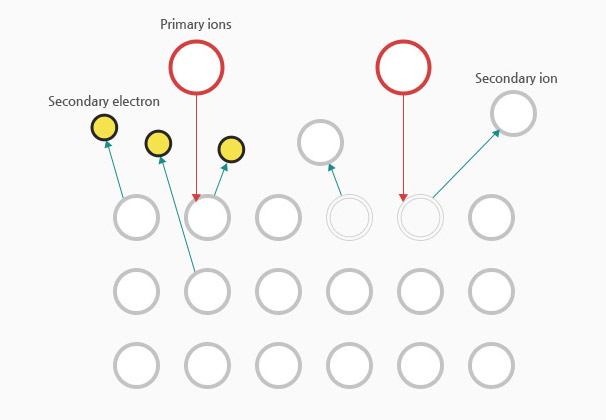
Electrons emitted from the cathode collide with Ar, resulting in Ar ionization.
Ar + e-(primary) = Ar+ + E-(primary) + e-(secondary)
As Ar gets excited and emits electrons, energy is released.
At this time, glow discharge occurs, emitting plasma of a specific color depending on the gas where the ions and electrons coexist.
Ar+ ions in the plasma are accelerated toward the target (cathode) by a large potential difference.
When Ar+ ions collide with the target's surface, neutral target atoms are ejected, forming a thin film on the substrate.
Sputtering Advantages and disadvantages
-
- Advantages
-
The deposition rate is stable and similar even on different materials.
Uniformed deposition is possible, ensuring excellent step or defect coverage.
Excellent thin film adhesion
It is possible to perform deposition on different materials such as metals, alloys, compounds, and insulators.
Target cooling is possible, enabling the use of large targets.
Pre-cleaning is possible through sputter etching of the substrate.
It is possible to form oxide and nitride thin films through reactive sputters such as O2, and N2.
-
- Disadvantages
-
The deposition rate is slow.(<10Å/sec)
Can be improved through magnetron sputteringHigh energy deposition causes non-uniformity and damage to thin films.
Heat treatment after deposition reduces non-uniformity and damageThin film heating is performed with exposure to electrons, UV, ions, etc. (100~150℃)
The substrate holder may require cooling.The deposition conditions are sensitive, and they can affect each other.
The sputtering parameters should be adjusted.
DC sputtering Advantages and disadvantages
-
- Advantages
-
It is the most standard sputter equipment with a simple structure.
The deposition rate is almost constant for various types of metals.
It is easy to control because the current amount and thickness of the thin film are almost in direct proportion.
The deposition rate is higher compared to RF sputtering.
High uniformity in thin films.
Ensures high adhesion since it requires high energy.
-
- Disadvantages
-
Target material is limited to metals.
High Ar pressure is required. (10 to 15 mTorr)
The substrate is prone to overheating.
RF sputtering
In DC sputtering, sputtering is not performed if the target is an oxide or an insulator.
This can be solved through RF sputtering. In particular, it can have a high sputtering yield value even at low pressure
since scattering is relatively reduced while the sputtered material reaches the substrate.
During DC discharge, although the secondary electrons are annihilated to the anode before supplying sufficient energy to the ionization process,
RF can be sufficiently used for ionization by reflecting electrons since the two electrodes have a negative potential compared to plasma.
RF sputtering can sputter non-metals, insulators, oxides, and dielectrics in addition to metals.
Although low MHz frequency is required, the United States Federal Communications Commission regulates operation of a high-frequency power source of 13.56 MHz
in order to avoid interference with radio frequencies in the commission's spectrum management.
High sputtering yield value is possible because scattering is relatively reduced when the sputtered material reaches the substrate.
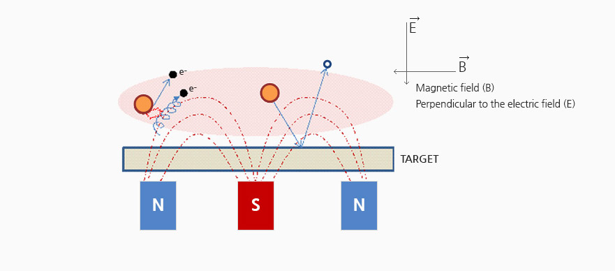
Magnetron sputtering
Magnetron sputtering is a method of increasing the sputter yield
by installing a permanent magnet or an electromagnet on the back of the target to increase ionization.
Electrons emitted from the cathode are collected locally in the magnetic field formed outside the target to promote collision with Ar atoms.
-
- Advantages
-
Increased sputtering efficiency.
Can reduce the collision of electrons on the substrate and thin film through the vortex motion of electrons.
Small effect of substrate temperature rise.
The deposition rate is high even in insulators such as SiO2 or Al2O3.
It is possible to perform sputter or reactive sputter of dielectric materials.
The deposition rate is constant at a given input power. (±10%)
Can reduce the thin film thickness through an appropriate array of permanent magnets and use of shield.
It is possible to adjust uniformity with ease.
-
- Disadvantages
-
The magnetic field must be made to enter and exit perpendicular to the target surface.
Target consumption is large through selective sputtering near the magnetic field. (Efficiency: approximately 25%)
Therefore, a thin target measuring 1/8″ ~ 1/32″ should be used.
Reactive sputtering
Unlike the roles of bias sputtering, reactive sputtering is used to form an oxide or a nitride thin film (such as dielectric thin film) according to purposes.
This method is the same as general sputtering, but reactive sputtering
can make a thin film of a desired compound by supplying a small amount of oxygen or nitrogen in addition to Ar.
Compound thin deposition through reactive sputtering is more advantageous
in terms of manufacturing, purity and price than directly sputtering an oxide or nitride target.
This is because gaseous atoms from the target are very unstable
and highly reactive to reactive gases, and atoms reaching the substrate also react quickly in thin film state.
If the substrate temperature is raised during reactive sputtering, it is possible to increase the deposition rate by increasing the compound formation rate.
However, reactive sputtering shortens the lifespan of filaments for vacuum pressure gauge or glow discharge,
and an insulating layer such as oxide or nitride is formed on the target surface during EC sputtering; thus reducing the sputter efficiency.
In DC sputtering, this phenomenon can be improved by rotating the permanent magnet
on the back side of the target from the initial stage of sputtering or by changing the magnet's current.
Magnetic material
Magnetic material is a generic term for materials that are magnetized in a magnetic field.
In a broad sense, air is also a magnetic material. Even though there is a difference in degree, we can say that all materials on Earth are magnetic.
However, the magnetism level (property of attracting magnets) varies greatly depending on the substance (material).
Materials exhibiting strong magnetism like iron are called ferromagnetic materials,
and materials with little magnetism like aluminum are called paramagnetic materials.
Here, paramagnetic materials are also called non-magnetic materials.
Among paramagnetic materials, there are materials that show diamagnetism, namely gold and copper, and they are referred to as diamagnetic materials.
Although diamagnetic materials are the complete opposite of ferromagnetic materials,
they are classified as paramagnetic materials since they have a very weak form of magnetism.
- Ferromagnetic materials
- Fe, Ni, Co
- Paramagnetic materials
- Al, Cr, Pt
- Diamagnetic materials
- Cu, Au, Ag
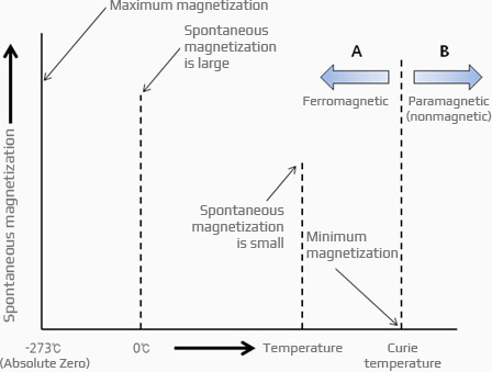
Relationship between spontaneous magnetization and temperature
If the temperature is below the Curie temperature, the spin waves of electrons of ferromagnetic materials, such as iron, are aligned in a specific direction.
The more spins it aligns, the easier it is for the magnetic material to become a magnet and magnetize in a small external magnetic field.
In this case, it can be regarded as a kind of atomic magnet since a mini-magnet is considered to have been formed in the spinning direction.
In brief, ferromagnets naturally possess magnetism, which is also referred to as natural magnetism.
Spontaneous magnetization has a temperature dependence
and reaches its maximum at -273°C (absolute temperature).
As the temperature rises, the magnetism decreases, and all magnetism is lost at the Curie temperature.
This is the point when a material becomes a nonmagnetic material (paramagnetic material).
Magnetizing
Magnetizing can be classified into three depending on the method. Magnetization is the alignment of atomic magnets.
In the case of atomic magnets in a magnetic material before magnetization, they are in a state wherein magnetic field lines are not spread outside (non-magnetized) as the north and south magnetic poles are tailed to each other.
If strong north and south magnetic poles are applied from the outside, however, these atomic magnets are aligned parallel to the magnetic poles
until structural changes occur wherein they can make the magnetic field lines flow outside.
Simply put, when a strong magnetic field is applied from the outside of a magnetic material
to align the magnetic poles of atomic magnets in a certain direction, it is called magnetization.
A commonly used method involves making a strong magnetic field
by flowing enough DC current into the coil and inserting a magnetic material into the magnetic field.
In some cases, as a method of weakening small ferrite material, magnetic materials come in direct contact
with a magnet such as Nd-Fe-B, which is a strong rare earth magnet, to make it temporary instead of using DC power.
Magnetic permeability
Magnetic permeability is a ratio of magnetic flux density and its corresponding magnetic force (magnetic flux density/magnetizing force),
indicating how easy it is to pass a magnetic field line.
Relative permeability is similar to magnetic permeability, wherein the permeability of a magnetic material is divided by the permeability in vacuum.
The highest relative permeability is Fe, with value of 120 to 20,000. For ferromagnetic substances, the relative permeability of cobalt is 270, and that of nickel is 180.
On the contrary, the relative permeability of paramagnetic (nonmagnetic) materials
such as aluminum or copper is close to 1, which is almost the same as air or vacuum.
Since aluminum and copper have very low transmittance, the magnetic field line easily penetrates even though they are metals.
In other words, they have no force to block the magnetic field lines.
On the contrary, the magnetic field lines cannot easily pass through ferromagnetic materials such as iron unless the materials cause magnetic saturation
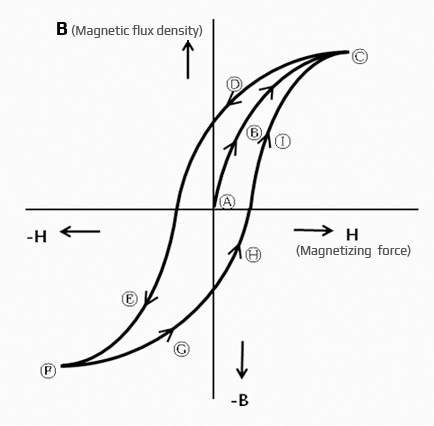
Hysteresis loop
In the case of gradually magnetizing ferromagnetic materials such as iron,
the relationship between magnetic flux density and magnetizing force exhibits
the same characteristics as 0 A B C.
If the magnetizing force is gradually decreased in saturated state (saturation point C), however, the magnetic flux density decreases according to the change to C D.
If the magnetizing force is further applied in the negative direction, F is reached via E. Iron (Fe) has the highest relative permeability with value of 120 to 20,000.
For ferromagnetic substances, the relative permeability of cobalt is 270, and that of nickel is 180.
On the contrary, the relative permeability of paramagnetic (nonmagnetic) materials
such as aluminum or copper is close to 1, which is almost the same as air or vacuum.
Since aluminum and copper have very low transmittance, the magnetic field line easily penetrates even though they are metals.
In other words, they have no force to block the magnetic field lines.
On the contrary, the magnetic field lines cannot easily pass through ferromagnetic materials such as iron, unless the materials cause magnetic saturation.
Magnetron sputtering
Generally, we can identify the characteristics of magnetic materials by using the hysteresis curve; in the case of permanent magnets, however, the B-H curve is used.
A good magnet refers to a magnet with strong magnetizing force proportional to the magnetic flux density.
Since the magnetizing force cannot stay stable when the coercive force is small despite having a large magnetic flux density,
however, a good magnet is a magnet that has high magnetic flux density and large coercive force.
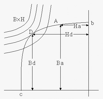
The curve below shows the demagnetization curve. The values of “b” and “H” at any point “A” on the curve are Ba and Ha.
At this point, the energy used becomes Ba x Ha, and this is called energy.
Bd x Hd at point “D” where Ba x Ha on the curve is maximum is called the maximum energy product, and it is indicated as “BHmax” with unit of “X10GOe.”
In order to get the energy product of any point on the demagnetization curve easily, we connect the points with the same BH and draw them in advance.
Here, if the external magnetic field is gradually reduced,
the magnetic flux density decreases from A to b.
If the external magnetic field is set to 0 (zero), it comes to the “b” point,
and the magnetic flux density of 0 (zero)b remains.
This value is called residual Induction, denoted by Br, and the unit is G (Gauss). If an external magnetic field in reverse direction is applied,
the magnetic flux density gradually decreases and comes to point “c”.
The strength of the external magnetic field in reverse direction required to reach “c”
is called coercive force and is indicated as Hc with unit of Oe (Oersted).